CONTENTS
1.2 Purpose of the Design Plan of the FSRU Seawater Intake
1.3 Structure of the Design Plan of the FSRU Seawater Intake
2....... Design, Rate and Location of the Seawater Intake. 3
List of Figures
Figure 1.1 Indicative Location of Key Project Components
Figure
2.1a Indicative Locations of the Seawater Intake (Top view)
Figure
2.1b Indicative Locations of the Seawater Intake (Starboard
side)
Figure 2.2a Diagram on Seawater Intake Process
Figure 2.2b Indicative Flow Direction of the Seawater Intake and Outlets (Starboard side)
Figure 2.3 Indicative Design of the Initial Intake Screen
Figure 2.4 Indicative Design of the Strainer
1.
Introduction
1.1
Background
To support the increased use of natural gas in Hong Kong from 2020 onwards, Castle Peak Power Company Limited (CAPCO) and The Hongkong Electric Co., Ltd. (HK Electric) have identified that the development of an offshore liquefied natural gas (LNG) receiving terminal in Hong Kong using Floating Storage and Regasification Unit (FSRU) technology (‘the Hong Kong Offshore LNG Terminal Project’) presents a viable additional gas supply option that will provide energy security through access to competitive gas supplies from world markets. The Project will involve the construction and operation of an offshore LNG import facility to be located in the southern waters of Hong Kong, a double berth jetty, and subsea pipelines that connect to the gas receiving stations (GRS) at the Black Point Power Station (BPPS) and the Lamma Power Station (LPS). The location plan is shown in Figure 1.1.
The Environmental Impact Assessment (EIA) Report for the Project was submitted to the Environmental Protection Department (EPD) of the Hong Kong Special Administrative Region Government in May 2018. The EIA Report (EIAO Register No. AEIAR-218/2018) was approved by EPD and the associated Environmental Permit (EP) (EP-558/2018) was issued in October 2018. An application for Further Environmental Permits (FEP) was made on 24 December 2019 to demarcate the works between the different parties. The following FEPs were issued on 17 January 2020 and the EP under EP-558/2018 was surrendered on 5 March 2020:
§ the double berth jetty at LNG Terminal under the Hong Kong LNG Terminal Limited, joint venture between CAPCO and HK Electric (FEP-01/558/2018/A) ([1]);
§ the subsea gas pipeline for the BPPS and the associated GRS in the BPPS under CAPCO (FEP-03/558/2018/B) ([2]); and
§ the subsea gas pipeline for the LPS and the associated GRS in the LPS under HK Electric (FEP-02/558/2018/A) ([3]).
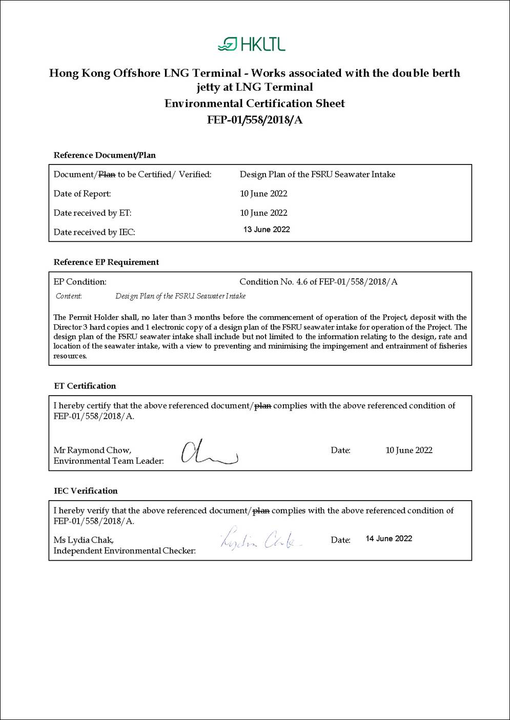
In accordance with Condition 4.6 of the FEP of the LNG Terminal (FEP-01/558/2018/A) (‘the Project’):
|
FEP No. FEP-01/558/2018/A, Condition 4.6: “The Permit Holder shall, no later than 3 months before the commencement of operation of the Project, deposit with the Director 3 hard copies and 1 electronic copy of a design plan of the FSRU seawater intake for operation of the Project. The design plan of the FSRU seawater intake shall include but not limited to the information relating to the design, rate and location of the seawater intake, with a view to preventing and minimising the impingement and entrainment of fisheries resources.” |
1.2
Purpose
of the Design Plan of the FSRU Seawater Intake
As stated in Condition 4.6 of the FEP of the LNG Terminal (FEP-01/558/2018/A), this Design Plan of the FSRU Seawater Intake presents the information relating to the design, rate and location of the seawater intake, with a view to preventing and minimising the impingement and entrainment of fisheries resources.
1.3
Structure
of the Design Plan of the FSRU Seawater Intake
The remainder of this Design Plan of the FSRU Seawater Intake is set out as follows:
§ Section 2 provides the design, rate and location of the seawater intake for the FSRU;
§ Section 3 summarises the design of the
seawater intake for the FSRU.
2.
Design, Rate and Location of the Seawater Intake
Based on the latest design of the FSRU vessel, seawater intake and outfall system is necessary to provide water to the regasification system by drawing water from the sea, and discharging back in the sea after use. The FSRU vessel is designed to have four (4) seawater intake points, two (2) at the port side and two (2) at the starboard side locating near the bottom of the FSRU vessel as shown in Figures 2.1a and 2.1b, to achieve a practical seawater intake rate for use in the regasification system while minimising the impingement and entrainment of fisheries resources. Each seawater intake point could be operated at an averaged flow rate of 5,000 m3 per hour. Depending on the LNG send-out rate, the intake points could be operated simultaneously to achieve a flow rate of up to 20,000 m3 per hour for the regasification process. The overall seawater intake process and flow direction of the seawater intake and outlets are illustrated in Figure 2.2a and Figure 2.2b.
Each seawater intake point has a sectional area of about 7,900 cm2 with an initial intake screen of about 30mm mesh gap size. The indicative design of the initial intake screen is presented in Figure 2.3. Upon drawing seawater through the seawater intake point, there is a strainer of about 4 mm mesh size to filter large particles that may damage equipment such as pump impeller and vaporizer. The mesh screens of the strainer are arranged in zig-zag to maximise the surface area for accommodating the required seawater flow rate and minimising impingement of fisheries resources. The indicative design of the strainer is presented in Figure 2.4. The use of coarse and fine screens will be able to reduce entrainment of larvae, eggs and juvenile fish while maintaining operational efficiency of the seawater intake system. Studies on fine mesh screens have shown that the fine mesh screens with mesh size of 0.5 mm to 5 mm installed have successfully reduced entrainment of larvae, eggs and juvenile fish up to 80% at the water intake structure ([4]).
The latest FSRU seawater intake design is in line with the preliminary design
presented in the approved EIA Report of the Project. Considering the low
sensitivity and productivity in ichthyoplankton and
fish post-larvae in the waters of the LNG Terminal, impacts are considered to
be of minor significance and unacceptable impacts due to impingement and
entrainment of fisheries resources are not anticipated. The use of
suitable screen mesh size and adjustable intake velocity depending on the LNG
send-out rate would help reduce the impingement and entrainment mortality of
fisheries resources, if present.
3.
Summary
The design, rate and location of the seawater intake for the FSRU has been discussed in Section 2. The latest FSRU seawater intake design and the flow rate of up to 20,000 m3 per hour are in line with the preliminary design presented in the approved EIA Report of the Project. Unacceptable impacts due to impingement and entrainment of fisheries resources are not anticipated.
([1]) Application for variation of an environmental permit for FEP-01/558/2018 was undertaken and the latest FEP (FEP-01/558/2018/A) was issued on 6 November 2020.
([2]) Application for variation of an environmental permit for FEP-03/558/2018/A was undertaken and the latest FEP (FEP-03/558/2018/B) was issued on 25 August 2021.